Articles

Ultimate MSX cartridge modification
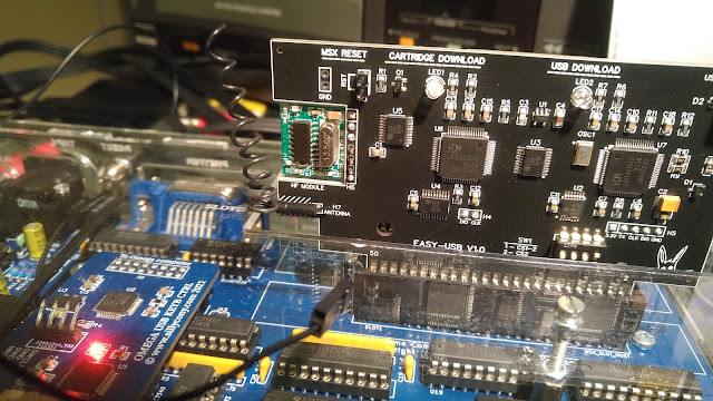
Image
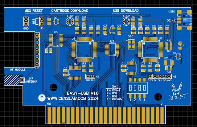
  I made two final changes to the design of this cartridge.  First modification. The first concerns the interfacing circuits with the MSX bus : Aoineko, the developer of the MSXgl graphics library who also tests the cartridge, reported to me problems with random startup of his computer. After studying his problem and especially after looking at the datasheet of his Panasonic FS-A computer, I realized that the power supply of this machine was 'unconventional' to say the least. This results in potential ground problems : I guess you 'see' what I mean. The wire that serves as a ground reference is one of the two wires of an AC power supply! Hmm, I don't like that at all.  With this type of design, the ground is always noisy for anyone who wants to connect to this type of device by taking the electrical reference of this ground.  I therefore powered the cartridge interface circuits no longer directly with +3.3V via the cartridge's internal regulator, but directly vi
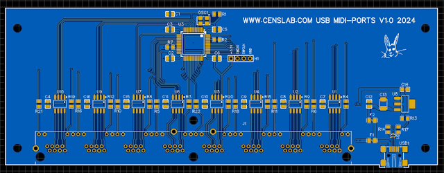
8 Ports USB Midi interface.

Image
  This topic is a very long-standing one for me. I must have started thinking about it in the early 90s. At the time, the power of microcontrollers did not allow the development of complex systems. I then remember having developed a 68000 system to manage the 8 MIDI ports. I never created this system because I realized that it was far too complex to create and therefore necessarily too expensive. 10 years later, at the beginning of the 2000s, things improved in terms of the possibilities of embedded systems. So I tried to create this multi MIDI port using a micro-controller. I almost got there, but ran into a small problem, it was still difficult to find a circuit offering 8 serial ports and fast enough to manage them. Everything changed in the early 2010s. At that time, it became possible to find a micro-controller circuit with 8 serial ports and enough power to manage everything. It was then that I looked into ARM type circuits from STmicro. From that point on, the p

A MSX flash cartridge downloadable from USB : the last iteration.

Image
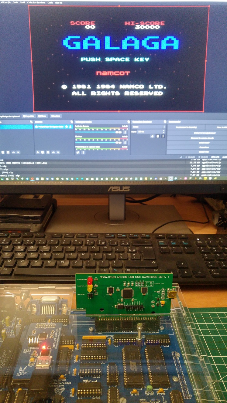
   What is it about this time? I did some redrawing work on certain tracks to make them more 'homogeneous'. I powered certain interface circuits directly via the +5V power supply from the MSX connector and no longer with the 3.3V coming from the 5V USB to 3.3V régulator. the goal being to avoid electrical level problems with the test machine, a Panasonic FS-A1. In theory, 3.3V interfacing should not pose any problems, but in reality, it does. And, I also added a small HF remote control module. This involves controlling remotely and without a physical link, an electrical outlet to automatically restart the MSX computer without having to manipulate the main switch, nor having to 'fiddle' with a RESET connection inside the computer. MSX.  The final circuit should look like this : Apart from the location of the HF module, the circuit looks almost the same as the previous version. Having written this, I also adjusted the external dimensions of the card so that

A MSX flash cartridge downloadable from USB.

Image
  We have to be honest, developing quality equipment is not easy. Downloading a cartridge directly via the USB port from your PC to the MSX computer without any manipulation to do is a good idea. But we must recognize that it is not done like that! I had to overcome hardware problems, software problems, implementation and component supply problems, etc. etc.  Fortunately, most difficulties come from not having in-depth knowledge of the issues encountered. This is the study side of 'study and development'. We're getting there but it takes time. So, after a certain number of prototypes, more and more functional, I am now arriving at the 'final touches'. What is it about? In fact, with the idea of ​​making the loading and restarting process of the MSX computer automatic, just after copying/pasting a ROM file, you have to... restart the computer. In 'real' life, a computer requires a power off/on sequence to restart on a new cartridge. This is not

UTC1122, AUTOMATION, RETRO COMUTING, MINIMAL COMPUTING.

Image
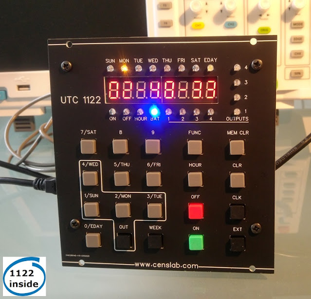
 A timer in an old-fashioned version, but up-to-date . For those who remember, at the end of the 70s and beginning of the 80s, at the time when the first microprocessors and microcontrollers arrived, the TMS1000 from T.I. appeared. It was a 'factory' programmable 4-bit microcontroller. A specific version, already programmed, was offered by T.I. under the name TMS1122. It was a timer capable of managing 4 outputs over a week. Given the limited resources of the circuit, the 'man-machine' interface was reduced to its simplest expression: A few keys, LEDs and 7-segment displays. Rustic? Today maybe, but at the time it was absolutely brilliant. But that is not the question. On the other hand, the important thing is that the method of entering information had to be designed to be as efficient as possible. This is called high constraint programming. And that's the whole point of this type of device: the ease of use. I therefore wanted to undertake the construction of a tim

Generic keyboard of 9x4 mechanical keys

Image
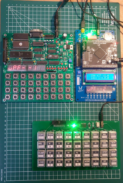
In 2022 one of my projects consisted of placing a Micro-Professor clone entirely in an FPGA. For this project, I created an external mechanical keyboard. Because the original membrane keyboard did not seem at all effective for working intensively with the machine. I know something about it, I learned the Z80 assembler on the 1P version in 1987. Memories... The keyboard, along with Wichit Sirichote's version of the mPF1 and my FPGA version. After publishing information on my FPGA version on the network, and after receiving some comments, especially about the keyboard, I decided to build a new version of it. This time with a processor that is easier to handle, a RISC-V in this case. This is what it should look like: This new keyboard will not be dedicated to a particular hardware type. It will provide its data in standard serial form but in RS485. This is to allow a certain immunity to noise as well as possible positioning quite far from the device to which it will be connected. Anot

ZX81 finally at home ;-)

Image
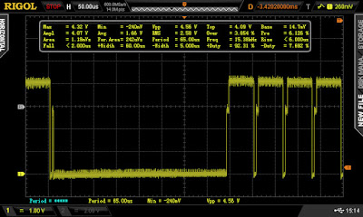
After doing some research on the popular modifications to be made on a ZX81, I decided to modify the video output in order to provide a composite video signal directly usable on a monitor with this type of input. Also, rather than increasing the RAM size to the usual 2KBytes, I decided to implement a 16Kbytes extension. As a reminder, the keyboard connectors are cut. So I ordered a new membrane keyboard (see previous post). Moreover, after checking the video signal at the output of the PLA (pin 16), I know that the video signal is correctly generated : In fact, after looking more closely at the video output, I could see that the cursor was indeed displayed. I was able to see 8 successive lines with this type of signal: So, I decided to set up inside the HF modulator, a small circuit intended to improve the quality of the composite video signal, in particular to solve the problem of the back porch. This type of circuit (ZX8-CCB) is available at this address .  It is also possible to mou